♪ NOW PLAYING 0 Old Flame Like A Dream ◉ VISITORS | *** thanks for stopping by my corner of the web *** best viewed at 800x600 *** sign my guestbook *** CPU Internals, Memory, and I/OEmbedded Systems Phase 2 covered how a processor executes instructions in isolation: ARM’s and the C55x’s register files, pipelines, and instruction sets. This phase looks at what’s actually attached to that processor. It covers how the CPU talks to devices outside itself, the privilege and exception machinery that keeps programs from corrupting each other, how memory is organized and cached, how logical addresses get translated into physical ones, and the deeper mismatch between sequential software and a concurrent physical world that interrupts exist to paper over. I/O Programming: From Polling to Buffered InterruptsEvery I/O device exposes at least two kinds of register to the CPU: a data register holding the actual payload, and a status register signaling ready/busy. A CPU can address these in one of two ways: dedicated I/O instructions with their own address space (x86’s The simplest way to wait for a device is busy-wait I/O (polling): the CPU repeatedly reads a status register until it flips to ready. It’s simple to reason about, but it wastes the CPU’s full attention on that one transaction, and the waste compounds badly the moment you’re servicing more than one device this way. Interrupts invert the relationship: instead of the CPU asking, the device tells the CPU when it’s ready, via an interrupt-request/interrupt-acknowledge handshake. The CPU saves the program counter much like a forced subroutine call, runs an interrupt handler (a device driver), and then returns to whatever the foreground program was doing. Push this further with buffered interrupt-driven I/O, a producer/consumer relationship built around a wraparound (circular) buffer with head and tail pointers, and input and output devices can run at their own independent rates while the foreground program gets on with other useful work entirely. That’s the natural progression: busy-wait, to basic interrupt, to buffered interrupt, each step decoupling the foreground program a little further from I/O timing. 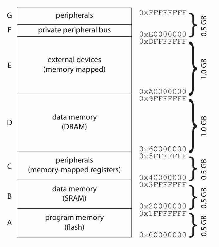 Two more axes of flexibility sit on top of the basic interrupt mechanism, and they’re independent of each other. Interrupt priorities let the CPU ignore or preempt lower-importance requests, with the highest priority reserved for the NMI (non-maskable interrupt), used for things like an imminent power failure. Interrupt vectors let the device itself, not the CPU, supply a number that indexes into a table of handler addresses. Priority decides which device wins when several want service at once; vectoring decides what code runs for a given device; most real CPUs implement both together. Debugging interrupt-driven code is uniquely hard for a reason worth naming directly: a register-corruption bug inside a handler manifests differently depending on exactly when the interrupt lands relative to the foreground program’s state, so the same underlying bug produces different wrong answers on different runs. You can’t find it by enumerating expected-versus-actual outputs the way you would a purely sequential bug. This is the practical, code-level version of the shared-variable races under asynchronous composition that showed up as an abstract hazard in Phase 1. Supervisor Mode, Exceptions, Traps, and Co-processorsMost CPUs enforce a hardware split between supervisor mode and user mode, so that buggy or malicious user code can’t corrupt shared state such as the MMU’s own registers. Certain instructions exist specifically to gate this boundary, like ARM’s An exception is an internally detected error, such as a divide-by-zero, and it uses the same underlying mechanism as an interrupt (a forced, vectored, prioritized control-flow change), the difference being that it’s triggered internally rather than by external hardware. A trap (a software interrupt) is an instruction that deliberately generates an exception, and its most common use is as the controlled gateway into supervisor mode: you don’t want user code jumping into supervisor mode through an arbitrary branch, so the trap instruction is the only sanctioned door. Co-processors extend an ISA with optional, tightly coupled execution units, floating point being the classic example, via reserved opcodes. On a CPU that doesn’t actually have the co-processor attached, an illegal-instruction trap can emulate the same opcode in software: the same instruction stream runs either way, falling back gracefully at a speed cost when the hardware isn’t there. Cache Memory: Hits, Misses, and the Structures Behind ThemA cache hit means the CPU finds what it needs already close by; a miss means it has to reach all the way to slower main memory, and that trade-off is captured directly in the average memory access time for a single-level cache with hit rate : Misses aren’t all the same, and it’s worth distinguishing their causes because each calls for a different fix. A compulsory (cold) miss is the first-ever reference to a location and is unavoidable. A capacity miss means the working set is genuinely bigger than the cache, calling for a bigger cache or a smaller working set. A conflict miss means two hot locations happen to alias to the same cache line, calling for more associativity or a better data layout. Wolf’s concrete version of a cache is direct-mapped: an address splits into tag, index, and offset fields, the index picks exactly one candidate block, and the tag confirms or denies a hit. It’s fast and cheap, but two frequently used addresses that alias to the same index will thrash each other out on every access, no matter how much other cache space sits idle. 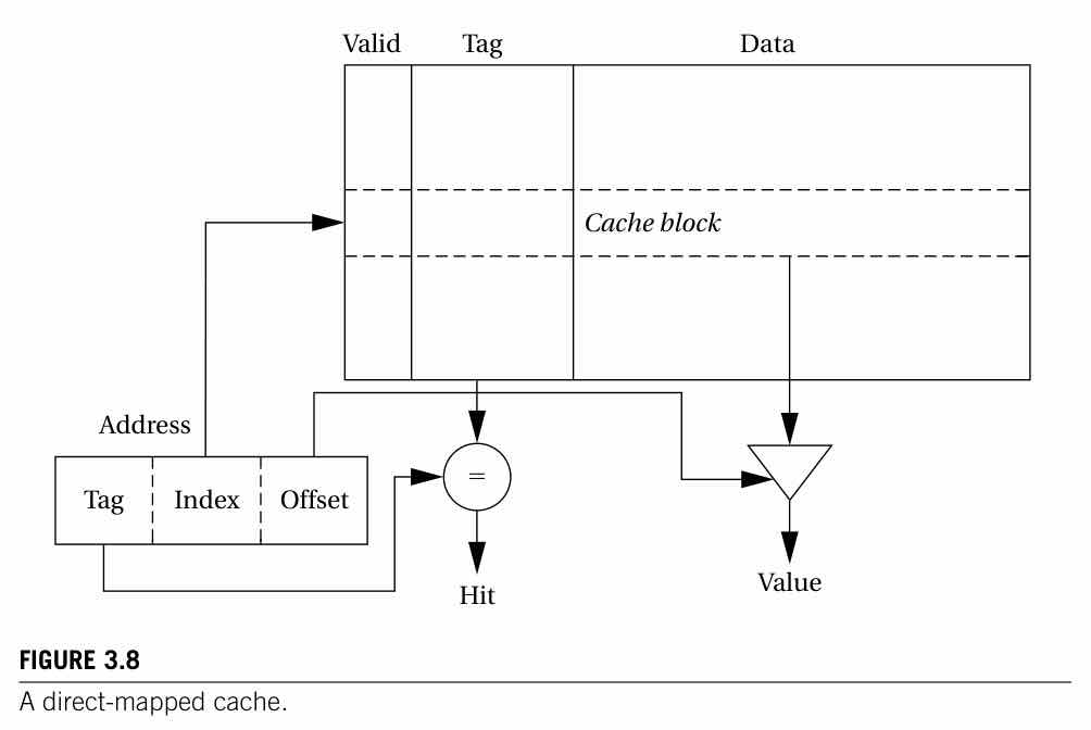 Set-associative caching fixes the thrashing problem: each index now maps to a set of lines, checked in parallel through a content-addressable lookup within the set, which absorbs the aliasing conflicts a direct-mapped cache suffers, at the cost of extra comparison hardware and a slightly slower cycle. Fully associative is the limit case, one set holding the whole cache, and it’s only practical for small structures like TLBs, since matching against every line in parallel gets expensive fast. When a set has more than one line, a replacement policy decides what to evict on a miss: LRU evicts whatever’s been unused longest, giving good hit rates at the cost of extra recency-tracking hardware, while FIFO or random replacement are cheaper but less effective. Separately, a write policy decides what happens on a write: write-through updates cache and main memory immediately, simple and consistent but generating more memory traffic, while write-back writes only the cache and flushes to memory on eviction, cutting traffic at the cost of a window where cache and memory disagree, and more complex eviction logic. Real designs often stack a second cache level on top of the first, and the same access-time formula extends naturally, with first-level hit rate and second-level-only hit rate : Lee and Seshia formalize the same tag/index/offset picture as a tuple : address width bits, sets, lines per set, block size bytes, giving an overall cache size of That formalization is worth having on hand because it turns “how many cache misses will this loop generate” into a computable exercise rather than a hand-wave, and it’s the version worth reaching for when reasoning about a specific cache’s behavior. 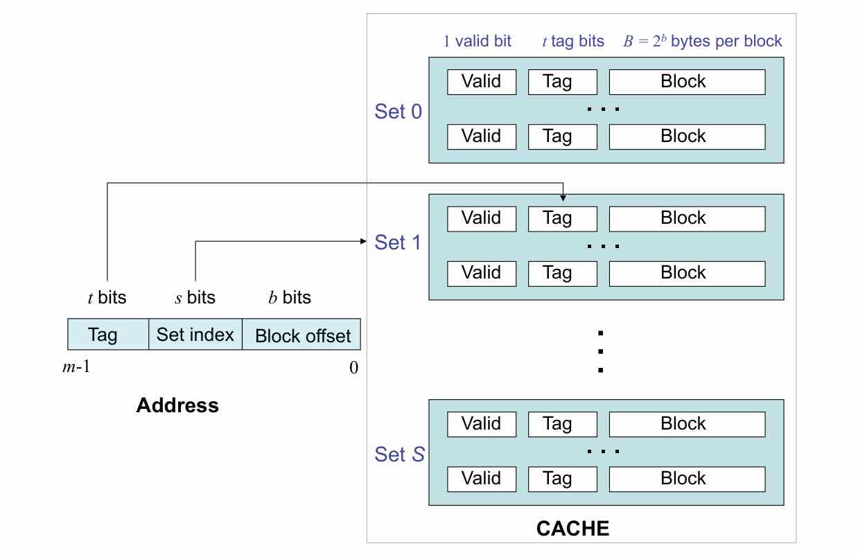 The point worth stating plainly is the predictability cost: caches can make memory access time vary by 1000x or more depending on hit or miss, which is exactly why a real-time embedded designer needs to understand cache behavior at a level a general-purpose programmer never has to. It’s the same throughput-versus-predictability tension from Phase 2‘s pipeline-hazard and ILP discussion, now showing up at the memory level. Scratchpads, software-managed “close” memory with no automatic hardware copying, are the predictable-but-tedious alternative to caches for exactly this reason. Address Translation: MMU, Segments, and PagesAn MMU translates the CPU’s logical (virtual) addresses into physical addresses in real RAM. Historically this existed to fit big programs into small address spaces; today its main jobs are giving each program a private, contiguous address space and supporting virtual memory, transparently swapping data between main memory and secondary storage. Two schemes exist for organizing that translation. Segments are arbitrary-sized regions addressed via a base-plus-bound register, needing one addition and one range check. Pages are uniform and small, so translation reduces to concatenating a page-table-supplied base with the low address bits, no arithmetic and no range check required. Segmented-paged schemes combine both, at the cost of fragmentation as pages scatter across physical memory. Page tables themselves can be organized as a flat structure (one entry per page, simple but large for a big address space) or a tree (multi-level, with some per-lookup overhead, but able to leave the unused parts of a sparsely populated address space unbuilt). It’s the same shape of trade-off as the direct-mapped-versus-set-associative cache choice: simple and fast against flexible and space-efficient. A TLB (translation lookaside buffer) is a small, fully associative cache specifically for page-table lookups, the direct analog of a data or instruction cache but caching translations instead of data. And a page fault, a requested page not resident in main memory, is handled exactly like any other exception: it’s vectored, the OS reads the page in from secondary storage, updates the MMU’s tables, and restarts the faulting instruction. MMUs and caches aren’t really two unrelated topics; they’re the same “small fast thing stands in for big slow thing, with a fault or miss escape hatch” pattern, applied twice. CPU Performance and PowerWolf grounds pipelining in ARM7’s own numbers: its 3-stage fetch/decode/execute pipeline gives each individual instruction a 3-cycle latency, but only a 1-cycle throughput once the pipeline is full. That latency/throughput distinction matters because performance analysis almost always cares about throughput, not any single instruction’s latency. Data stalls, where a multi-cycle instruction like load-multiple holds up decode of what follows, and control stalls (branch penalties), where a branch’s target isn’t known until execution reaches it so already-fetched sequential instructions get thrown away, are the same data- and control-hazard categories from Phase 2, now visible as concrete ARM pipeline diagrams; the two chapters’ hazard material is really one unit. Wolf’s own worked example for hand-counting a loop’s cost, an initiation cost plus per-iteration body and update costs times , plus worst-case exit tests and one best-case test, gives: The specific formula matters less than the pattern it encodes: fixed setup, plus per-iteration cost times , plus one asymmetric exit case, which is the general recipe for hand-counting a loop’s cycle cost. CPU power draw is derived directly from CMOS circuit behavior. Dynamic power is proportional to the square of supply voltage, which makes undervolting the single biggest lever available: A 10% voltage cut buys roughly a 19% power cut. Dynamic power is also proportional to switching activity, but slowing the clock only cuts power, not total energy, since the same work now just takes longer, an important distinction for battery-life reasoning versus heat-dissipation reasoning. Leakage power persists even when the chip is idle, and is only fully eliminated by cutting power entirely. Power state machines formalize the resulting trade-off: states are operating modes, each labeled with an average power draw, and transitions are labeled with the time cost of switching between them. The StrongARM SA-1100, for instance, saves over 1000x power in sleep versus run, but takes over 100 ms to wake back up. That asymmetry, cheap to fall asleep, expensive and slow to wake, is the recurring shape of nearly every real power-management scheme, not just this one chip. Memory Technology and the C Memory ModelMemory splits first into volatile and non-volatile, with a nuance worth keeping in mind on the volatile side: SRAM is fast and holds data as long as it’s powered, but is larger per bit, while DRAM is slower and denser but needs periodic refresh even while powered, which arguably makes it “more volatile” than SRAM, since refresh timing itself introduces access-time variability, another predictability tax. On the non-volatile side, mask ROM is fixed at the factory and used for firmware, while EEPROM and flash are field-writable but with write time far exceeding read time and a finite write-count, typically much lower for NOR flash than NAND. Each of these picks a different point on the same speed/persistence/write-endurance surface. A chip’s address space is statically carved up into a memory map: fixed regions for program memory (often flash), data memory (SRAM or DRAM), and memory-mapped peripheral registers. Real silicon usually populates only part of what the architecture allows for; an ARM Cortex-M3 chip, for example, might implement only 256 KB of the architecture’s 0.5 GB flash region, leaving the rest reserved. That’s the concrete, real-chip version of the ISA-versus-realization distinction from Phase 2. Register file size, too, is constrained by more than circuit cost: an ISA that lets one instruction reference 3 registers out of 16 spends 12 of its instruction-word bits just naming registers, which is exactly why register files stay small even though the silicon cost of adding more is trivial. The C memory model is worth walking through in one pass, because embedded code leans on all of it. Global variables get a fixed, compiler-assigned address. Local and automatic variables, and by convention parameters, live on the stack in per-call stack frames, pushed and popped LIFO; returning a pointer to a local variable is a classic dangling-pointer bug the moment its frame is popped. Heap-allocated data from I/O Hardware and the Sequential/Concurrent MismatchSome I/O is about producing analog-like effects from digital pins. PWM (pulse-width modulation) delivers effectively variable analog power through a digital pin by varying the fraction of time the signal is high, its duty cycle. It works whenever the driven device’s physical response is slow relative to the PWM frequency, motors, heating elements, and LEDs all average the rapid switching into an effectively steady level, which is a good general test for whether something can be PWM-driven. A handful of GPIO practicalities bite in real designs often enough to be worth knowing up front: current and voltage limits (Ohm’s law constrains what a pin can drive directly), electrical isolation between noisy or high-power domains and sensitive logic (opto-isolators, transformers), and Schmitt-triggered inputs, which add noise hysteresis to inputs, the same hysteresis idea as a thermostat applied to signal integrity instead of temperature. Open-collector (open-drain) outputs only ever pull a line low and rely on a shared pull-up resistor, letting multiple devices safely share one line without risking a short; it’s the deliberate wired-NOR/wired-AND pattern used for things like a shared-bus “any device can request shutdown” safety line. Tristate logic generalizes this further by letting a driver disconnect entirely, supporting both high and low sharing rather than just low. Serial (one line, bits sequenced in time) dominates today even though it sounds slower than parallel, because pin and wire count is a hard constraint on embedded packages, and because keeping many parallel lines synchronized gets harder, not easier, as cable length grows. It’s a good example of intuition pointing the wrong way. Whenever multiple devices share one line, a bus needs a media-access control (MAC) policy: single-master polling (as in USB), time-triggered slots, token ring, priority arbiter, or CSMA (sense, then transmit, then back off on collision). It’s the hardware-bus version of the same scheduling problem that reappears at the software task level in Phase 6. DMA (direct memory access) lets a peripheral transfer data to or from memory without CPU involvement in each byte, freeing the CPU to do other work during the transfer, but a DMA transfer competing for the memory bus can silently stretch the timing of any CPU code that also needs memory access during that window: a sneaky, easy-to-overlook source of timing variability distinct from cache or pipeline effects. All of this is in service of a central thesis Lee and Seshia state directly: software is sequential by nature, the physical world is concurrent by nature, and interrupts are the primary mechanism for reconciling the two. That reconciliation is a major risk area in embedded system design, not an edge case. Atomicity in particular is not obvious, and it’s a recurring source of real bugs: even a single C statement like That recommendation has a direct, satisfying payoff back in Phase 1‘s hierarchical state machine material: modeling an ISR’s interaction with the foreground program as a hierarchical FSM works cleanly, because the asymmetry that the ISR can interrupt the main program but not vice versa is exactly a preemptive transition with reset into the ISR’s refinement. Lee and Seshia’s own worked example builds this model out and it actually finds a real bug: there’s no guarantee that a “do something for 2 seconds” loop ever reaches its exit state if interrupts arrive faster than the ISR can drain them. It’s the single best argument either book makes so far for why the formal modeling machinery from Phase 1 is worth having, not just academically interesting. 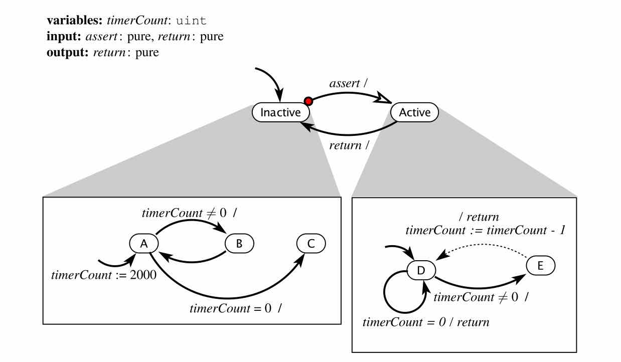 Where This Leaves UsThe throughline connecting nearly every topic in this phase is the same one: hardware features that improve average-case performance, caches, pipelines, interrupts, DMA, all do so by introducing timing variability, and reasoning about (or outright avoiding) that variability is the central skill this phase is building toward. Wolf supplies the concrete ARM and C55x mechanics and the classic performance and power formulas; Lee and Seshia supply the more general, ISA-independent vocabulary, the cache tuple, the C memory model, the sequential-software-versus-concurrent-world framing, plus the genuinely new payoff of modeling interrupt/foreground interaction as a hierarchical FSM to find a real correctness bug. Their own worked example stops short of resolving the bug it finds, and mitigations like watchdog timers or priority ceiling protocols are worth returning to once scheduling is on the table. Phase 4 picks up right where the I/O hardware discussion here leaves off: the buses and protocols that actually carry data between the CPU and the sensors and actuators sitting at the edge of the physical world. ← Instruction Sets & Processor ArchitectureIndexBuses, Memory-Mapped Devices, Sensors & Actuators → |