♪ NOW PLAYING 0 Old Flame Like A Dream ◉ VISITORS | *** thanks for stopping by my corner of the web *** best viewed at 800x600 *** sign my guestbook *** Networking & Distributed Embedded SystemsEmbedded Systems Phase 7 was about splitting work across processing elements that share a common memory. This phase asks the next question: what happens when the processing elements can’t share memory at all, because they’re physically scattered around a car, a plane, or a building, and have to coordinate purely by sending messages over a wire? That’s Wolf’s definition of networking, and it turns out to reuse a surprising number of ideas already built up in earlier phases, just applied one layer further out. Networks Versus Buses, and Why Bother DistributingWolf is precise about a distinction that’s easy to blur: a “network,” in this chapter’s sense, is an interconnection scheme without shared memory. By that definition, the microprocessor bus from Phase 4 is technically a network too, but the networks this chapter cares about are ones where processing elements (PEs) must communicate by explicit message passing rather than by reading and writing a common address space. The distinction matters practically: PEs on a genuine network don’t fetch instructions over it the way a CPU fetches over its bus, and that absence of arbitrary instruction and data fetch traffic is exactly why network timing tends to be more analyzable than bus timing. The reasons to distribute go beyond the accelerator and multiprocessor motivations from Phase 7. Putting a PE physically next to the sensor or actuator it serves avoids building an expensive, fast link to a distant CPU. Doing initial signal processing locally means only reduced data has to cross the network at all. A network port is also a cleaner component boundary than exposing an internal bus, which makes debugging easier (one PE can probe or stimulate another directly) and improves fault tolerance, since a failure in one PE doesn’t necessarily propagate through shared memory to every other PE. Even when a network looks “too simple to need it,” it’s worth keeping the OSI seven-layer model in mind as a checklist: physical, data link, network, transport, session, presentation, and application, from lowest to highest abstraction. Wolf’s point is that even minimal embedded networks implement physical, data-link, and network-layer functions whether or not anyone labels them that way, and any embedded system that talks to the Internet needs the full stack regardless. 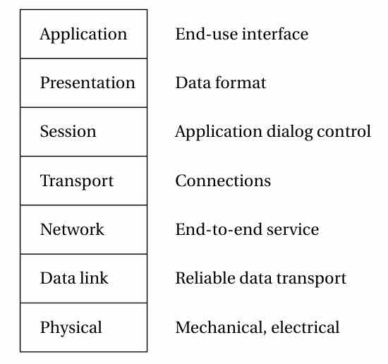 Topologies, Arbitration, and Push Versus PullNetwork topologies trade generality against cost along a single spectrum. Point-to-point links are the simplest option, needing no arbitration at all, and make sense when the communication pattern is fixed and known in advance, as in Wolf’s filter-pipeline example. A bus is shared and needs arbitration, but costs only one link’s worth of hardware. A crossbar is fully non-blocking, letting any PE talk to any other simultaneously, but its cost grows as the square of the port count. A multistage network sits in between, using intermediate routing nodes as a cost-and-generality compromise between a bus and a crossbar. The property that actually distinguishes these options is blocking versus non-blocking: a bus is maximally blocking, since any message in flight blocks all others, while a crossbar is non-blocking by construction. Arbitration schemes fall into the same two camps CPU scheduling did back in Phase 6: fixed-priority arbitration is simple but can starve a low-priority device indefinitely under sustained high-priority traffic, while fair or round-robin arbitration avoids starvation at some cost to throughput. It’s the same fixed-versus-fair tension, just moved down to the network-arbitration level. Single-CPU programs default to a pull model, reading data when they want it, but networked systems often favor push instead: nodes broadcast periodically-sampled data unprompted. Push suits periodic sensor data naturally and cuts out request/response round-trip traffic, and Wolf’s automotive sensor-network example, impact sensors and engine data streaming out continuously, is the canonical case where push is obviously the right call. A related, higher-level idea is running multiple segregated networks rather than one: a cheap, slow network for non-critical traffic alongside a separate network for critical or high-volume traffic. This is the network-level version of the same cost-segregation argument from Phase 7 that many cheap PEs beat one expensive PE; isolating critical traffic onto its own simple, analyzable network is often both cheaper and more predictable than trying to run everything over one high-performance shared network. Two Protocols Worth Knowing in Detail: I²C and EthernetI²C is about as minimal as a real network gets: two wires (SDA for data, SCL for clock), open-collector or open-drain signaling, and multi-master capability. The signaling is the same wired-AND trick used for sharing GPIO lines in Phase 4, and I²C puts it to clever use for arbitration: a transmitting master listens to its own transmission, and if it ever hears a different bit than the one it sent, it immediately backs off. Arbitration is resolved during the address transmission itself, with no separate arbitration phase needed, purely by exploiting the electrical property that lets multiple open-drain outputs share a line safely. Flow control gets an equally minimal solution: a slave can stretch the clock’s low period (never the high period) to buy itself more processing time, a mechanism baked directly into the electrical protocol. Ethernet works differently because its nodes are unsynchronized, so collisions can’t be caught within a single bit time the way I²C catches them. Instead Ethernet uses CSMA/CD (Carrier Sense Multiple Access with Collision Detection): wait for silence, transmit, keep listening while transmitting, and abort with a backoff if a collision is detected. The mechanism that keeps the network from collapsing under contention is exponential backoff: the wait time grows exponentially with the retry count and is randomized (or “dithered”) so that the same two colliding nodes don’t just collide again on the next attempt. Wolf gives this only a qualitative shape rather than a precise formula, roughly: That is, the contention window doubles per retry (bounded in practice), and a uniform random draw is taken within that window. The combination of exponential growth (avoiding sustained overload) and randomization (avoiding repeat collisions between the same pair of nodes) is a generically reusable congestion-control pattern worth recognizing anywhere contention and retry show up, not something specific to Ethernet. The consequence for real-time use is significant: Ethernet’s collision-driven, randomized retry timing makes worst-case delivery time fundamentally hard to bound, so standard Ethernet was never designed for real-time guarantees. Every “real-time Ethernet” variant works by doing one of three things: suppressing collisions entirely, reducing how often they occur, or resolving them deterministically instead of randomly. It’s a concrete instance of a lesson that has echoed through the pipeline, cache, and scheduling discussions of earlier phases: mechanisms that optimize average-case throughput, like random backoff, directly undermine worst-case predictability, and making such a mechanism real-time-friendly usually means trading some of that throughput and flexibility back for determinism. CAN Bus: Arbitration Built Into the WireCAN is the chapter’s deepest example, and it’s worth understanding closely because it turns the same wired-AND trick from I²C into a genuine hardware priority scheduler. CAN signals use recessive (1) and dominant (0) levels wired-AND: if any node drives a 0, the whole bus reads 0. That single electrical property is what makes CAN’s arbitration scheme work at all. The scheme itself is called CSMA/AMP (Arbitration on Message Priority). Every node wanting to transmit sends its message’s 11-bit identifier synchronously, bit by bit, alongside every other contending node. The instant a node trying to send a recessive (1) bit hears a dominant (0) bit from someone else, it silently drops out of contention. By the end of the identifier field, exactly one transmitter remains, and the identifier has doubled as a fixed message priority the entire time (an all-zeros identifier is the highest priority). This is a more sophisticated version of I²C’s arbitration: the same wired-AND trick, but turned into a deterministic, priority-based scheduling mechanism for the bus itself, directly paralleling fixed-priority CPU scheduling (rate-monotonic scheduling) from Phase 6, just implemented in the electrical layer instead of in software. 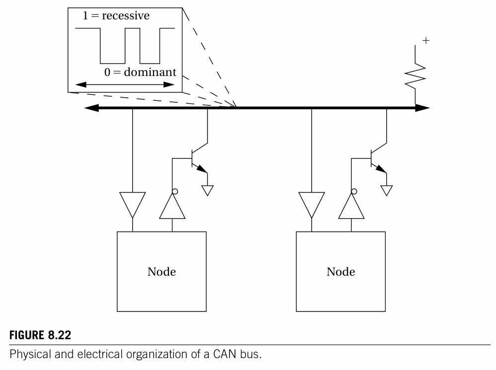 The CAN frame structure is worth remembering conceptually rather than memorizing bit-for-bit: an arbitration field (the identifier plus a request/write-like RTR bit), a control field (length), a data field (0 to 64 bytes), a CRC for error detection, an acknowledge field, and an end-of-frame marker. The acknowledge field has a neat property of its own: a receiver signals success by not overriding a recessive ACK bit, so silence means success and an active dominant pulse means “I caught an error, please retransmit.” CAN also supports a remote frame, a request without parameters addressed purely by identifier, which reinforces that CAN, like I²C, is fundamentally a data-push, publish-by-identifier protocol rather than a general request/response one. Error and overload frames round out CAN’s resilience story. Any node that detects an error can interrupt an in-progress transmission to flag it immediately, and a node that’s falling behind can send an overload frame to explicitly signal “not ready yet” and buy itself more time. This is CAN’s answer to the same flow-control problem I²C solves with clock-stretching, just solved at the framing level instead, since CAN’s synchronous, priority-based bus has no single clock line available to stretch. The Automotive and Avionics Network ZooReal vehicles don’t run one network; they run several, which is the “segregated networks” principle from earlier in this chapter applied to an actual mass-produced product. CAN itself runs at up to 1 Mb/s and handles general control traffic. Alongside it sits FlexRay (up to 10 Mb/s, deterministic and fault-tolerant, effectively CAN’s real-time-hardened successor), LIN (a cheap, single-wire, low-rate, master-initiated-only network for simple, localized subsystems like a single door), and MOST (a ring topology running tens to hundreds of Mb/s, used for infotainment). Automakers don’t try to run engine-control-critical CAN traffic and infotainment MOST traffic over the same physical network, and that separation is deliberate. Avionics differs from automotive in a way that’s worth being precise about, because the difference is procedural rather than technical. Every permanently-attached avionics component requires type certification (of the design) and production certification (of each individual unit). That certification burden is why avionics architectures stay conservative, favoring separate line replaceable units per function, even in cases where a more integrated, networked design would be technically superior. It’s a useful reminder that architecture decisions are sometimes driven by regulatory and process constraints external to the engineering problem itself, not purely by cost, performance, or power. Closing: From Wired Arbitration to Provable CorrectnessThis phase is best read as Phase 7’s direct sequel: multiprocessing answers “how do I split work across several PEs sharing memory,” and networking answers “how do I split work across several PEs that can’t share memory at all.” Nearly every mechanism here turns out to be a variant of something already established elsewhere in this series. OSI layering is a more formal restatement of the abstraction-layering theme that has run through the whole plan since Phase 2. Bus arbitration, fixed-priority against fair or round-robin, directly parallels CPU scheduling from Phase 6. I²C’s and CAN’s wired-AND arbitration both reuse the exact open-drain electrical trick from Phase 4’s GPIO sharing discussion. And the Ethernet real-time discussion is one more instance of the throughput-versus-predictability tension that has surfaced in every phase since Phase 2’s pipeline hazards. The one genuinely new idea this phase adds is that arbitration and scheduling can be implemented directly in the electrical or physical layer, not just in software: CAN’s CSMA/AMP is a priority-based scheduler built entirely out of wired-AND logic and synchronized bit timing, rather than a kernel data structure. Everything covered so far, instruction sets, memory systems, multitasking, multiprocessors, and now networks, has been about getting embedded systems to work, and to work predictably. The next question is how to actually prove that they do: Phase 9 turns to formal methods for verifying correctness, moving from “this design should behave predictably” to “here is a proof that it does.” ← Multiprocessors & SoCIndexVerification & Correctness (Formal Methods) → |